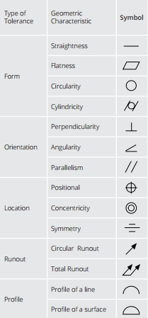
Geometric Dimensioning and Tolerancing (GD&T) is a design approach and manufacturing mechanism that helps engineers and designers communicate how to bring a part design to life. When documented correctly using GD&T, it is possible to build a part that exactly matches its on-paper plans.
The drawing is the controlling document that ensures the vendor is creating precisely what the customer’s design requires. Machinists and quality engineers will use GD&T, print dimensions, and drawing notes to develop a manufacturing process and inspection methodology that will construct high-precision components matching the designer’s original vision. Proper print detailing will also help with measurement correlation to aid in the communication between customer and vendor.
GD&T uses a symbolic language to indicate how significantly part features can deviate from the geometries listed in the design model. This language contains all relevant details involved in fabrication, including dimensions, tolerances, definitions, rules, and symbols that communicate a component’s functional requirements. These all currently follow ASME Y14.5M-2009 (previously ASME Y14.5M-1994).
Engineers and designers look to GD&T to design critical aspects of a part’s features, including a specific feature’s desired location, form, profile and orientation. It is common practice to use the profile designation tied to the datum structure that is related back to the solid CAD model. This allows Manufacturing to use a best fit protocol.
Five Major Advantages
 GD&T, a vital part of complex machining, offers a number of major advantages:
- Saving Money — GD&T enhances design accuracy by allowing for appropriate tolerances that maximize production. For many projects, the process provides extra or bonus tolerances, further increasing cost effectiveness.
- Ensuring Dimensional and Tolerance Requirements — By explicitly stating all design requirements, a thorough GD&T process guarantees accurate fulfillment of all dimensional and tolerance specifications.
- Assisting Digital Design Methods — Clear, concise GD&T data is readily adaptable to digital design programs, including nearly universally used 2D and 3D CAD files.
- Offering Uniformity and Convenience — As a single, consistent language, GD&T reduces guesswork and interpretation while ensuring consistent geometries across design and manufacturing.
- Providing Accurate Communication — Today’s intricate designs demand the most accurate and reliable communication. GD&T enables designers, manufacturers, and inspectors to communicate clearly with one other, saving time and making the process more efficient.
When to Use GD&T
While many applications benefit from GD&T, there are certain situations in which the process provides fundamental assistance, including scenarios in which critical or interchangeable parts fit into a larger assembly, tolerance analysis needs simplification, or the project requires functional gauging techniques.
GD&T replaces complex description notes with a single symbol or set of symbols, allowing for effortless reference and fast, precise communication. The process provides additional clarity when clients are working without a standard interpretation or tolerance, making even the most in-depth and complicated projects easier to complete.
GD&T at Ardel Engineering
Ardel Engineering specializes in precision machining that meets the closest tolerances. As experts in the GD&T process, we are happy to discuss how incorporating the symbolic language will benefit your specific project. Contact our team of experts today to learn more.
To find out more and to see the rest of the chart above, download our latest eBook, Cost-Effective Tips for Machining Complex Parts.


